
Views: 0 Author: Site Editor Publish Time: 2026-06-28 Origin: Site
A spinning or loose fastener, often called a "spin-out," stands as a highly disruptive failure in field applications and scaled manufacturing environments. Dealing with a seized bolt turning endlessly inside a compromised panel wastes valuable time and resources. When specified correctly and installed using calibrated tooling, these fasteners provide permanent, high-strength threads in thin materials. Loosening rarely indicates a product flaw. It almost always serves as a symptom of incorrect application, tolerance mismatch, or simple installation error. We will decode the mechanical causes of this fastener failure below. You will discover preventative engineering strategies to stop spin-outs before they start. Finally, we provide a decision framework for specifying the right hardware, such as properly selected Rivet Nuts, to guarantee absolute assembly integrity.
Defining a "loose" fastener requires engineering precision. A loose joint does not just rattle. It signifies a complete loss of clamp load or unwanted rotational freedom. Engineers categorize these failures by the direction of movement. Understanding how the joint moves helps us pinpoint the exact failure mode.
Spin-out occurs when the fastener rotates entirely within the base material. You typically see this when a mating bolt cross-threads during assembly. Operators applying excessive torque will also break the friction lock. Corroded bolts are another major culprit. When maintenance teams try to remove a rusted bolt, the torque required to break the rust often exceeds the rotational resistance of the fastener itself. The entire unit then spins uselessly.
Pull-out happens when the fastener pulls completely through the host material. This represents an axial failure. Using hardware bearing an insufficient flange size is a common cause. Another trigger involves exceeding the base material's shear strength. If you install a heavy-duty steel fastener into a very thin, soft aluminum sheet, a heavy axial load will tear the host metal before the fastener breaks.
Dynamic loads create severe challenges for any mechanical joint. Vibration loosening causes the mating bolt to slowly back out over time. While the primary fastener might stay fixed in the panel initially, the loss of clamp load introduces rattling and shifting. This continuous micro-movement eventually compromises the upset bulge holding the insert in place. Proper clamping force must be maintained to protect the structural integrity of the blind-side bulge.
| Failure Mode | Primary Direction | Common Trigger | Symptom |
|---|---|---|---|
| Spin-Out | Rotational | Over-torque, cross-threading, rust | Fastener turns freely when bolt is turned |
| Pull-Out | Axial | Overloading, small flange size | Fastener rips entirely through the panel |
| Vibration | Dynamic / Multi-axis | Lack of thread locking, low clamp load | Bolt backs out, joint rattles loose |
Hardware fails for specific, preventable reasons. Identifying the root cause requires auditing the entire installation process. Here are the four primary reasons these joints fail in production environments.
Common Mistake: Relying on standard twist drills for thin sheet metal creates lobed, uneven holes. Always use step bits or laser cutting for precise circular geometry.
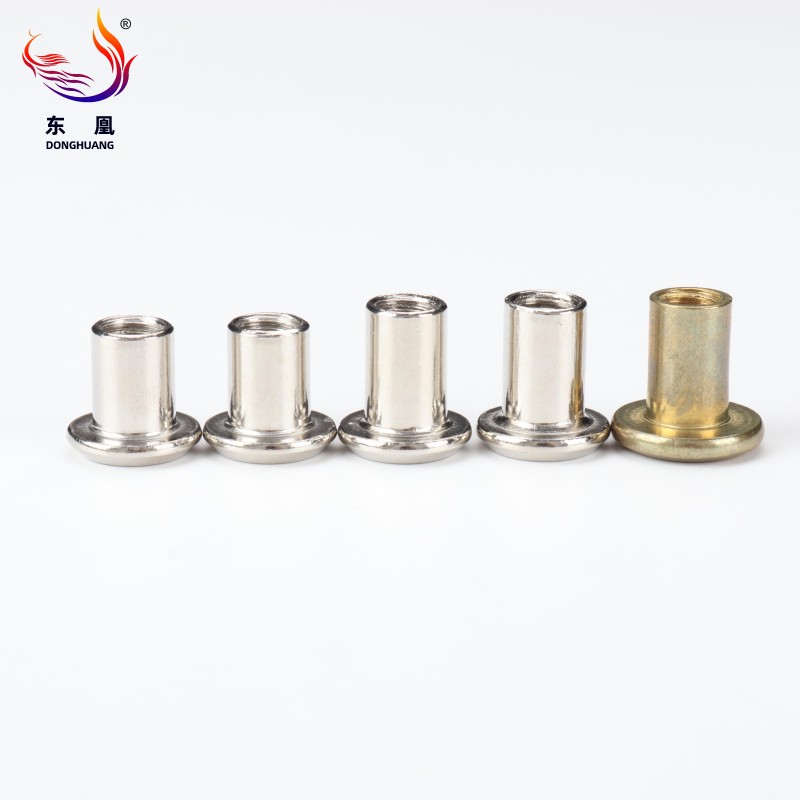
When standard smooth-body designs fail to meet torque requirements, engineers must upgrade the fastener body geometry. Selecting the right body style provides an immediate boost to rotational resistance.
Ribbed designs represent the easiest upgrade path for existing assembly lines. Vertical knurling covers the external body of the fastener. During compression, this knurling bites aggressively into the host material. The displaced metal locks the fastener in place.
Hexagonal bodies eliminate spin-out entirely. You install these into laser-cut or punched hexagonal holes. The geometric interference provides an absolute mechanical lock against rotation. High-quality Rivet Nuts featuring full-hex designs endure extreme torque specifications without failing.
Some applications cannot accommodate hexagonal holes. Keyed fasteners offer a specialized alternative. They feature a small mechanical key situated directly beneath the head flange. You prepare the host material by cutting a standard round hole featuring a small notch. The key slots firmly into this notch during installation.
Encountering a spinning fastener presents an immediate logistical headache. Implementation realities dictate we address the seized bolt without damaging the surrounding host panel. The approach changes drastically based on whether you face an isolated field failure or a recurring production line defect.
Field technicians must utilize friction techniques to stop the spinning temporarily. Some apply strong superglue under the flange, letting it cure to hold the body temporarily. Others carefully wedge a flathead screwdriver beneath the flange to apply outward pressure, locking the blind-side bulge against the panel just long enough to remove the seized bolt. Specialized extraction tools also exist, gripping the flange securely during bolt extraction.
When friction hacks fail, you must remove the fastener completely. The drill-out method remains the safest approach.

