
Views: 0 Author: Site Editor Publish Time: 2026-06-28 Origin: Site
Securing components into thin-sheet panels presents a notoriously difficult engineering challenge across multiple industries. Traditional threaded fasteners easily pull through thin metal gauges under minimal stress, causing immediate joint failure. Choosing the wrong fastener directly leads to compromised structural integrity, sudden assembly bottlenecks, or incredibly costly rework. Engineers and procurement teams frequently weigh standard blind rivets against threaded inserts to resolve this common dilemma. This crucial decision hinges entirely on whether the specific assembly requires a permanent joint or future component removal. In this article, we will thoroughly define the mechanical differences and compare load capabilities between these two options. We will evaluate specific tooling requirements needed for safe, consistent installation. Finally, we provide a clear, actionable framework for specifying exactly the right fastener for your production or fabrication needs.
Understanding the mechanical operation of each fastener prevents catastrophic design failures down the line. Both operate on a "blind" installation principle. You only need access to one side of the material to secure them. However, their internal mechanisms differ drastically.
Selecting hardware based on visual similarity invites structural failure. We must evaluate performance based on directional load dynamics and downstream lifecycle requirements. Each fastener type excels in distinct mechanical environments.
Force interacts differently depending on the fastener design. Standard rivets handle shear loads exceptionally well. Shear force pushes two joined panels in opposite lateral directions. The solid body of the expanded rivet strongly resists this lateral slicing motion. They remain ideal for structural panel joining. You use them primarily when panels are never intended to separate. Aerospace and heavy transportation manufacturing rely on this sheer strength daily.
Conversely, threaded inserts handle high pull-out forces. We call this tensile resistance. Tensile force attempts to pull a bolt straight out of the mounted hole. We evaluate threaded anchors based heavily on thread strength. Torque-out thresholds matter just as much as basic joint clamping force. A high pull-out resistance makes them exceptional for mounting heavy secondary attachments onto thin frames.
| Performance Metric | Standard Blind Rivets | Threaded Inserts |
|---|---|---|
| Primary Load Resistance | Excellent shear strength (lateral forces) | Excellent tensile strength (pull-out forces) |
| Joint Type | Overlapping panel joining | Anchor point for secondary components |
| Vibration Resistance | Exceptionally high | Moderate to high (depends on bolt torque) |
| Torque Capacity | Not applicable | High (especially with hex-body designs) |
Standard blind hardware offers absolutely zero reusability. Removal forces technicians to drill out the central core entirely. This destructive process destroys the fastener completely. You must then meticulously clean out the resulting metal shavings. This reality limits their use to permanent, tamper-resistant assemblies.
Threaded inserts boast massive reusability advantages. They enable infinite assembly and disassembly cycles for the end-user. This specific trait remains absolutely essential for removable access panels. Automotive mounting brackets demand this exact operational flexibility. Modular electronic enclosures require frequent internal servicing. Heavy machinery components must undergo routine maintenance or replacement over their product lifecycle.
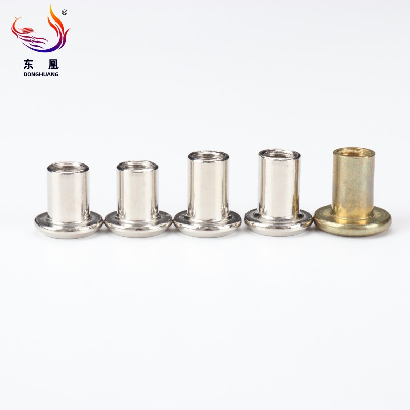
Tooling realities dictate your entire installation success rate. Procurement teams often misunderstand the equipment crossover. A massive compatibility gap exists on the shop floor. A standard rivet gun simply cannot install threaded inserts. Attempting to mix tooling inevitably destroys delicate internal threads. It also causes incomplete body collapses, leading to loose joints.
Standard installation tools prioritize simple stroke length. They focus heavily on sheer pulling force to snap mandrels. You can easily find cheap manual hand-squeezers for small prototype jobs. High-volume production floors utilize pneumatic or hydro-pneumatic automated rigs. The internal mechanism remains fairly straightforward and requires minimal daily calibration. Operators learn to use these tools in minutes.
Threaded insert installation requires a much more complex internal mechanism. The tools must perform a precise Spin-Pull-Spin operation. They thread into the nut, pull back to collapse it, and spin outward safely. Advanced models use a Pull-to-Pressure mechanism instead of a fixed stroke. This ensures consistent collapses regardless of slight material thickness variations.
Evaluation Note: Procurement must carefully factor in long-term tooling costs. High-volume installation demands significant capital investment upfront. You need high-quality, pressure-controlled pneumatic tools on your assembly line. These specific tools actively prevent under-collapsing. They also stop catastrophic thread stripping entirely. Attempting to save money on cheap tools results in astronomical rework costs.
Even properly specified fasteners fail when implementation goes wrong. Understanding common failure modes allows engineers to build mitigation strategies directly into the assembly process.
The "Spin-Out" risk remains the most common failure mode for threaded inserts. A spin-out occurs when the installed nut rotates freely inside its hole. If the hole is slightly oversized, severe problems arise. Excessively soft parent material also contributes directly to rotational failure. Under-torqued installation tools leave the collapse bulge dangerously incomplete. When a technician inserts a bolt and tightens it, the entire nut simply spins in place. Removal at this stage becomes incredibly difficult and damages the parent panel.
Solution: Use specialized hex-body inserts whenever possible. You can also deploy splined or ribbed bodies in high-torque environments. These geometric shapes bite and lock into the material effectively. They physically cannot spin unless the parent material tears completely.
Grip range miscalculation consistently ruins entire assemblies. Both fastener styles maintain strict minimum and maximum material thickness limits. Selecting a fastener with an improper grip range always invites disaster. Selecting a grip range that is too long results in dangerously loose joints. The hardware rattles and fails under minor vibration. Conversely, a grip range that is too short heavily crushes the parent material during installation. Always verify your exact material thickness before ordering any hardware batches.
Galvanic corrosion destroys joint integrity silently over time. Combining mismatched metals heavily accelerates this chemical breakdown. Placing bare aluminum hardware into carbon steel panels invites aggressive rust. Moisture in the air acts as an electrolyte to speed up the process. The fastener material must strictly match the parent material whenever possible. If matching proves mechanically impossible, you must utilize appropriate protective coatings. Zinc plating or specialized paints act as reliable separation barriers. They effectively prevent rapid galvanic reactions in harsh outdoor environments.
| Failure Mode | Primary Cause | Mitigation Strategy |
|---|---|---|
| Spin-Out | Oversized holes, under-torqued tools, smooth hardware | Use hex-body designs, calibrate tooling pressure |
| Loose Joint | Hardware grip range is too long for the panel | Measure panel thickness accurately, select smaller grip |
| Crushed Material | Hardware grip range is too short for the panel | Select larger grip range, use load-spreading designs |
| Corrosion | Mismatched metals (e.g., aluminum and steel) | Match materials, apply zinc-nickel protective coatings |
Procuring hardware requires more than just browsing a catalog. You must align your purchasing decisions with specific engineering parameters. We recommend evaluating these three core considerations before committing to a design path.
Standard blind rivets stand out as the economical, high-shear choice. They provide exceptional lateral holding power for permanent structural joints. Threaded inserts remain the required engineering solution for modular assemblies. They excel when thin-sheet materials demand robust, reusable load-bearing threads. Understanding these fundamental mechanical differences eliminates costly rework.
Take direct action before issuing your next purchase order. Precisely measure your parent material thickness using digital calipers. This vital step defines your exact required grip range safely. Assess your existing shop-floor tooling capabilities realistically to avoid compatibility gaps. Finally, always test a small batch for torque-out resistance in your specific parent material before full production begins.
A: Yes, though it is not their primary purpose. They can clamp two thin sheets together securely. However, a standard bolt is still required to maximize the joint's utility. Without inserting the secondary bolt, the internal threads remain entirely unused, and the assembly acts as a significantly over-engineered, hollow permanent fastener.
A: A rivet stud operates on the exact same blind-installation principle as a threaded insert. However, it leaves an externally threaded post protruding from the material. This male stud differs from an internal female thread. It allows you to quickly slide secondary components over the protruding stud and secure them externally using a standard hex nut.
A: Removal requires carefully drilling through the upper flange. You must use a drill bit matched perfectly to the exact outside diameter of the nut body. This precision allows the top flange to break off cleanly. The remaining collapsed body then simply falls through the blind side of the parent material.
A: While standard round holes work perfectly for general applications, they are not always ideal. Heavy-duty applications often utilize pre-punched hexagonal holes combined with hex-body threaded inserts. This specific geometric combination completely eliminates any rotational failure or "spin-out" risks, even under extreme torque loads.

