
Views: 0 Author: Site Editor Publish Time: 2026-06-25 Origin: Site
Specifying the wrong fastener for thin or brittle materials does not just slow down assembly. It leads directly to structural failures, annoying spin-outs, and highly frustrating rework. These mechanical errors easily compromise entire production schedules. While Rivet Nuts provide incredibly reliable, load-bearing threads in blind applications, selecting the correct variant requires absolute precision. You must align strict mechanical specifications perfectly alongside your daily production realities. Overlooking basic compatibility metrics creates severe joint vulnerabilities in final product designs. This guide provides a definitive evaluation framework to help engineering teams specify optimal fasteners. You will discover exactly how to evaluate baseline load requirements, assess crucial material compatibility, and select proper installation tooling. Following these verified engineering principles guarantees lasting structural integrity across all your complex blind fastening applications.
Traditional tapping requires minimum material thicknesses. Most modern sheet metals simply lack the physical depth for cut threads. Engineers struggle constantly to tap robust threads into thin metal panels. The threads strip almost immediately under tension. Standard nuts and bolts demand dual-sided access. You must physically reach behind the panel to hold the nut. Closed-box profiles make this action entirely impossible. Extruded aluminum tubes block rear access completely. This creates a significant engineering hurdle during assembly.
You can solve these exact engineering issues by deploying Rivet Nuts. The application might require extremely robust load-bearing threads. The host material could be incredibly thin. Examples include sheet metal, thick plastics, or advanced composite panels. The assembly process might provide access from only one side. Industry professionals call this a "blind" installation. You simply drill a hole and insert the fastener from the front. The specialized tool compresses the insert mechanically. It forms a secure structural bulge tightly behind the panel. This provides permanent, reusable internal threads.
You must carefully rule out other common fastening options. Use standard blind rivets solely for joining two panels together. They provide zero reusable threads for secondary component attachments. Consider traditional weld nuts if high-heat manufacturing processes remain acceptable. Weld nuts provide excellent strength. However, the extreme welding heat warps thin sheet metal instantly. The welding process also destroys pre-painted surfaces. It damages galvanized coatings permanently. Weld nuts also strictly demand weldable parent metals. You cannot weld a steel nut onto a fiberglass panel. Threaded inserts install entirely cold. They protect your delicate surface treatments completely.
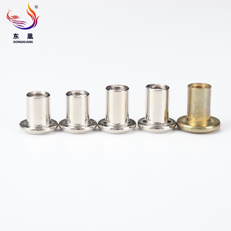
Material selection drives the entire lifecycle of your joint. Aluminum variants are incredibly lightweight and naturally resist rust. They work perfectly alongside plastics. They match soft parent metals easily. However, aluminum remains entirely unsuitable for high tensile loads. The internal threads strip rapidly under heavy mechanical stress. Zinc-plated steel provides standard, dependable high strength. It serves as the absolute standard across general manufacturing environments. You must verify the zinc plating thickness carefully. Thin plating degrades quickly during outdoor environmental exposure. Stainless steel alloys deliver maximum corrosion resistance and sheer physical strength. Marine, medical, or food-grade applications absolutely require 304 or 316 stainless grades. You must beware of galvanic corrosion constantly. Improperly pairing dissimilar metals creates a microscopic battery effect. Connecting stainless steel directly to plain aluminum accelerates rust exponentially. Always match your fastener material closely to your parent panel.
| Material Type | Primary Benefit | Common Application | Known Limitation |
|---|---|---|---|
| Aluminum | Lightweight, rust-proof | Plastics, soft metals | Low tensile strength |
| Zinc-Plated Steel | High mechanical strength | General manufacturing | Vulnerable to harsh weather |
| Stainless Steel | Maximum corrosion defense | Marine, medical, food-grade | Risk of galvanic corrosion |
You need to measure the exact thickness of your host material. Use calibrated digital calipers to acquire the most precise measurements. Never guess or estimate this critical metric. Paint layers often add unexpected thickness to panels. Under-sizing creates a highly dangerous mechanical situation. The insert cannot reach far enough behind the panel. It fails to form a proper compression bulge. You risk sudden, catastrophic pull-out under load. Over-sizing poses equally dangerous threats to structural integrity. The uncompressed body leaves a noticeable gap. The fastener rattles loosely inside the mounting hole. It will eventually spin freely.
Match your thread pitch perfectly to the mating bolt. You can specify standard metric sizes easily. You might prefer imperial specifications for older designs. Define your acceptable pull-out thresholds long before ordering parts. Establish exact torque-out limits based on verified engineering tables. Evaluate how much rotational force the fastener will experience. A large thread size inside a weak material fails quickly. The surrounding panel will yield long before the bolt breaks. Always balance thread dimensions against parent material limitations.
Rotational failure remains a massive issue in blind fastening. The insert rotates inside the panel when you tighten the bolt. We call this a spin-out. You can prevent this by selecting the optimal body shape.
The head style dictates how the joint distributes dynamic loads. Flat heads provide the highest possible push-out strength. They distribute heavy clamping loads across a very wide surface area. They sit slightly proud of the parent material surface. This leaves a tiny gap under flush-mounted secondary components. Countersunk or low-profile heads solve this clearance issue completely. They allow for perfectly flush mating of all secondary components. Secondary brackets sit entirely flat against the primary panel. However, countersunk variants demand incredibly precise hole preparation. You must machine a perfect countersink angle into the panel. The host material must possess sufficient thickness to accept the countersink taper. Thin sheet metal cannot support a countersunk head safely.
Your fastener choice directly dictates your necessary installation tools. You cannot separate fastener selection from tooling compatibility. Installing a stainless steel insert requires significantly more force than an aluminum one. A standard tool might install aluminum effortlessly. That same tool will fail to compress stainless steel completely. You must verify tool pulling capacity against material hardness.
Production risks run high without proper tooling protocols. You must train factory operators thoroughly. They need to calibrate the precise stroke length accurately. They must adjust the pulling force based on specific material hardness. Different grip ranges demand unique tool configurations on the line. A poorly calibrated pneumatic tool ruins panels instantly. It either under-compresses the insert or crushes the internal threads completely. Regular tool maintenance prevents widespread batch failures.
Evaluating potential suppliers requires strict diligence and engineering oversight. Look exclusively for valid ISO certifications when vetting new manufacturers. ISO 9001 certification ensures proper factory quality management systems exist. Ask suppliers directly for verifiable load-testing data. Never accept theoretical strength estimates for critical structural joints. Lot traceability remains absolutely critical for long-term quality control. If a fastener fails in the field, you must trace its exact manufacturing batch. Traceability allows engineers to isolate defective runs quickly.
Establish a strict prototyping protocol for your engineering team. Always request physical sample batches first. Test these specific samples directly in your actual production materials. Use your actual production-grade tools during these initial validation tests. Do this long before placing any bulk factory orders. Verify the pull-out strength manually. Test the torque-out limits using a calibrated torque wrench. This hands-on testing exposes hidden material incompatibilities immediately.
Take clear technical actions today. Audit your current bill of materials (BOM) thoroughly. Look actively for logical ways to consolidate internal thread sizes. Standardizing on fewer sizes reduces tooling changeovers dramatically. It streamlines your entire assembly floor operations. Request comprehensive technical specification sheets from your chosen manufacturers. Compare exact grip ranges and ultimate tensile strengths side-by-side.
| Action Phase | Key Requirement | Expected Outcome |
|---|---|---|
| Supplier Audit | Verify ISO & Lot Traceability | Ensures consistent manufacturing quality |
| BOM Review | Consolidate redundant thread sizes | Reduces tooling changeovers on the floor |
| Prototyping | Test samples with production tools | Validates grip range and torque thresholds |
Selecting the right fastening inserts fundamentally balances mechanical strength and precise material compatibility. It also aligns heavily with your specific assembly line tooling capabilities. Ignoring any of these three pillars guarantees downstream assembly failures. Do not rely on guesswork or estimations for critical grip ranges. Never assume baseline torque ratings without physical proof. Base all structural decisions on verified manufacturer load data. Contact our engineering team to review material-specific testing data. Request a comprehensive sample kit today. Validate your specific application requirements before finalizing any structural designs.
A: A standard blind rivet permanently joins two pieces of material together. It leaves a smooth head. A blind threaded insert installs into a single piece of material. It provides a highly reusable, load-bearing internal thread. This allows you to attach a secondary bolt or screw easily.
A: To prevent spin-out, ensure the hole is cut to the exact manufacturer tolerance. For high-torque applications, upgrade directly to a splined body or a hex-body variant. You must also ensure the installation tool is properly calibrated to fully compress the insert against the panel.
A: Yes, but you must use specialized variants. Splined bodies, pre-bulbed slotted variants, or inserts featuring incredibly wide grip ranges are strictly required. These specific designs distribute the heavy clamping load safely. They prevent the fastener from cracking or crushing the brittle host material.
A: If the grip range is too small, the insert will not reach the back of the material. It cannot form a secure bulge, leading to immediate pull-out. If the grip range is too large, the fastener will not compress tightly. This results in a loose fit and eventual spin-out.

