
Engineers constantly face a frustrating challenge in structural design. Creating strong, reusable, load-bearing threads in thin, brittle, or tubular materials is notoriously difficult when you can only access one side of the assembly. Traditional tapped threads fail in thin metal sheets because they lack sufficient material thickness to grip a fastener securely.
You might consider weld nuts, but welding requires high heat, poses severe safety risks, and destroys delicate surface finishes. Assembly lines need a reliable, non-thermal alternative. Rivet Nuts, also known as blind threaded inserts, perfectly fill this mechanical void. They install completely from one side and provide robust, heavy-duty threads without hot working.
This guide breaks down the precise mechanical principles of blind threaded inserts. We explore how they function, compare them to traditional fastening methods, and provide a comprehensive engineering framework. You will learn how to evaluate their suitability for high-volume production lines and critical structural applications to ensure long-term assembly success.
Closed-tube framing, aluminum extrusions, and thin sheet metal components share a common design constraint. Reaching the backside of the material is physically impossible. Assembly requires fasteners capable of setting themselves without rear support. We call this a "blind" fastening concept. Blind fasteners act as permanent anchors. They install from the front face and expand behind the panel to lock themselves in place.
The core mechanism relies on controlled plastic deformation, often referred to as upsetting. The fastener features a threaded lower section and an unthreaded, thinner-walled upper section. When force is applied, the thin wall yields before the heavy threads do. Here is the exact four-step mechanical sequence:
Best Practice: Always ensure the host material sits completely flush against the primary head of the insert before actuating the tool. An angled installation causes uneven collapse and severely reduces load capacity.
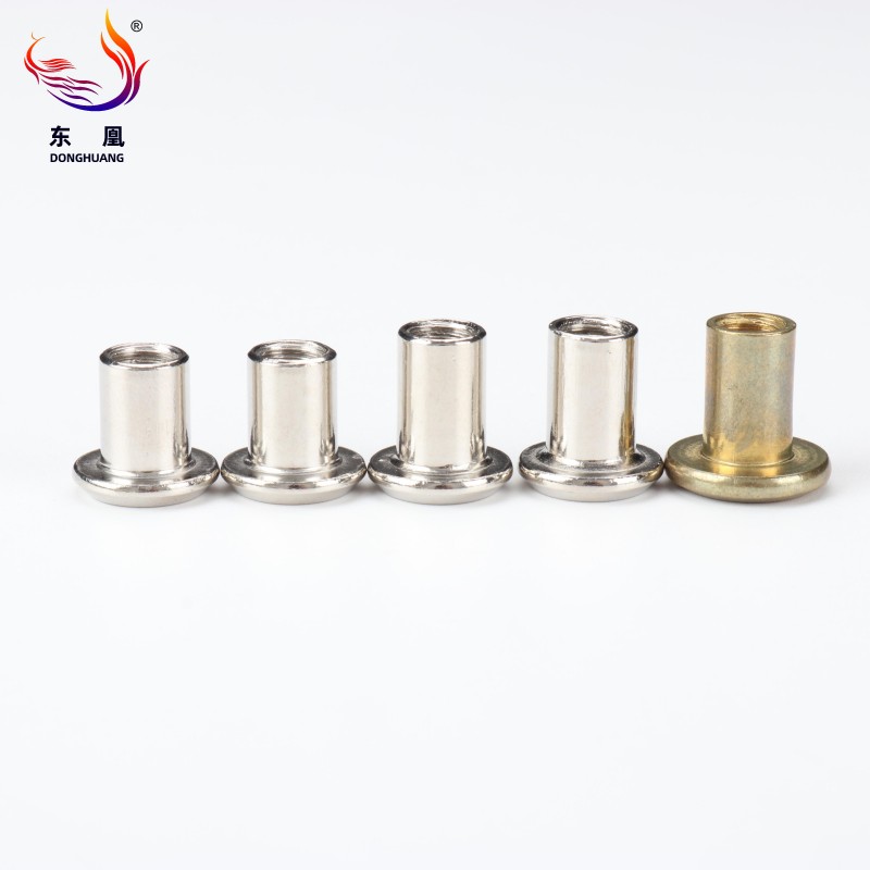
Engineers must carefully weigh assembly speed, environmental factors, and structural integrity when choosing a fastening method. We can compare blind threaded inserts against three traditional alternatives to highlight their specific mechanical advantages.
Weld nuts introduce immense thermal stress into an assembly. The welding process alters the metallurgical grain structure of thin sheet metal, leading to warping and heat distortion. Safety protocols complicate matters further. Welding generates toxic fumes, dangerous sparks, and requires strict hot work permits on the factory floor.
Blind inserts eliminate heat entirely. You avoid distortion and bypass complex safety compliance. More importantly, you preserve the surface finish. Operators can install them directly into pre-painted, galvanized, or powder-coated materials. Welding ruins coatings and demands costly secondary touch-up painting.
Self-tapping screws offer a cheap way to join thin materials, but they suffer in dynamic environments. Repeated maintenance cycles quickly strip the thin threads formed in sheet metal. Once the threads strip, the fastening point is permanently ruined.
Blind inserts provide a much stronger solution. They offer permanent, reusable machine threads. They distribute clamped loads over a wider surface area. This results in superior vibration resistance and much higher pull-out strength compared to standard sheet metal screws.
Through-bolting requires an operator to hold a wrench on the backside of a panel while tightening the bolt from the front. This dual-sided tool access severely limits design geometry. It also requires two hands, or sometimes two operators, significantly dragging down assembly line speed.
Blind fastening removes the need for rear access. An operator secures the insert from the front, speeding up cycle times. The assembly design becomes much cleaner because engineers no longer need to design access hatches or wrench clearances.
| Fastening Method | Blind Installation | Reusability | Heat-Free Process | Vibration Resistance |
|---|---|---|---|---|
| Rivet Nuts | Yes | Excellent | Yes | High |
| Weld Nuts | No | Excellent | No | High |
| Self-Tapping Screws | Yes | Poor | Yes | Low |
| Through-Bolts | No | Excellent | Yes | Medium |
Selecting the correct fastener involves evaluating several overlapping mechanical variables. A poor choice in body type or material leads directly to premature field failure.
Torque-out occurs when a fastened bolt turns, but instead of tightening, it spins the entire insert inside the host material. You prevent this by selecting the correct body geometry.
Every blind threaded insert features a specific grip range. This range dictates the exact material thickness it can safely clamp. If your panel is thinner than the minimum grip range, the fastener will not clamp tightly, resulting in a loose joint. If your panel is thicker than the maximum grip range, the unthreaded wall cannot collapse fully. The insert will fail to form a structural flange. Always measure panel thickness accurately, accounting for applied paint or plating.
Fastener material must match the host material and the environmental exposure. Placing dissimilar metals in contact creates a galvanic cell, leading to rapid corrosion when moisture is present. For example, never use a standard zinc-plated steel insert in a bare aluminum marine chassis. The aluminum will act as an anode and corrode away aggressively.
Match materials logically. Use aluminum inserts for aluminum panels. Choose 316 stainless steel for highly corrosive marine or chemical environments. Select brass for electrical conductivity and specific non-sparking applications.
The visible head of the fastener dictates flushness and push-out strength.
The most robust fastener in the world fails if installed improperly. Tool selection directly impacts your production speed, installation consistency, and operator fatigue.
Tooling ranges from simple hand squeezers to fully automated robotic end-effectors. Your production volume dictates your choice.
Understanding tool actuation methods ensures quality control across varying material tolerances.
Stroke-Controlled Tools: These tools pull the internal mandrel a specific, pre-set distance before stopping. They work excellently when panel thickness remains perfectly uniform. However, if your sheet metal supplier delivers a batch of material slightly thicker than usual, a stroke-controlled tool might fail to collapse the insert fully.
Pressure-Controlled Tools: These tools pull until they reach a specific resistance or clamping force, regardless of distance. They adapt dynamically to slight variations in panel thickness. Pressure-control ensures a tight, consistent clamp every single time, making it the preferred choice for high-reliability manufacturing.
Anticipating failure modes allows engineers to build robust mitigation strategies into the assembly process. Most failures stem from incorrect specifications or improper hole preparation rather than a defect in the fastener itself.
Cause: Spin-out occurs when an operator over-torques the mating bolt during final assembly. It also happens frequently when using smooth-body inserts in high-vibration, high-torque applications. The insert breaks internal friction and rotates freely.
Prevention: Upgrade to splined or hex-body fasteners for any high-torque requirement. You can also integrate chemical thread-locking compounds on the mating bolt to reduce the torque required to achieve a secure hold.
Cause: Pull-out happens when axial loads literally tear the fastener out of the panel. This usually results from incorrect hole sizing. An oversized hole reduces the surface area available for the collapsed flange to grip. It also occurs if you select an insert with an inadequate grip range for the host material.
Prevention: Strictly adhere to manufacturer hole tolerances. Utilize precision laser-cut or mechanically punched holes. Avoid hand-drilled holes. Hand drills frequently create oval or oversized openings that compromise joint integrity.
Cause: Over-upsetting destroys the fastener during installation. Applying excessive pulling force causes the internal threads to compress, strip, or shear entirely. The mating bolt will then fail to thread into the damaged insert.
Prevention: Ensure proper calibration of pneumatic or battery-operated tools. Base your force settings precisely on the specific insert material and thread size. Aluminum requires far less pulling force than stainless steel. Test your settings on scrap material before moving to live production parts.
Blind threaded inserts provide tremendous business and engineering value. They solve complex blind-fastening problems while keeping assembly lines moving fast. By eliminating welding, you maintain material integrity, avoid toxic fumes, and skip expensive secondary painting processes. You achieve permanent, load-bearing machine threads in materials otherwise too thin to tap.
Your shortlisting logic should follow a strict sequence. First, determine your exact panel thickness to establish the required grip range. Second, calculate your required torque specifications to choose between smooth, knurled, or hexagonal bodies. Finally, evaluate your production volume to dictate your tooling investment, leaning toward pressure-controlled pneumatics for high-volume environments.
Take actionable steps to secure your assembly process. Consult with a specialized fastener engineer to review your specific load cases. Request physical samples to perform pull-out and spin-out testing in your actual host materials. Verify your current hole tolerances and conduct a thorough audit of your factory floor assembly tooling.
A: Yes. You can remove a damaged insert without ruining the base material. Carefully drill through the primary head using a drill bit matching the original hole diameter. Once the flange detaches, use a punch to push the remaining collapsed body through the back of the panel. You can then install a new fastener into the existing hole.
A: Absolutely. Load-bearing capacity depends heavily on thread size, fastener material, and host material limits. In many structural scenarios, the thin base material yields or tears before a high-quality steel or stainless steel insert actually fails.
A: Yes. While DIY friction-wrench methods exist for one-off emergency uses, they are highly prone to angled installations and thread damage. Reliable, repeatable installation on a production level absolutely requires a dedicated setting tool to apply precise linear pulling force.
A: "Rivnut" is a proprietary trademark originally developed by B.F. Goodrich in the 1930s for the aerospace industry. The terms "rivet nut" or "blind threaded insert" serve as the generic, non-trademarked industry terms for this exact same fastening technology.

